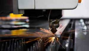
What is Press Brake?
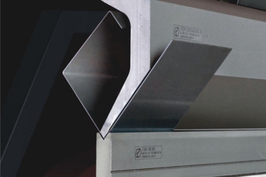
A press brake is a piece of manufacturing machinery that bends sheet metal. A press brake is usually narrow and long enough to allow large pieces of sheet metal to be bent by it.
A press brake bends the sheet metal by lowering a punch onto the sheet metal which is placed on top of the die. The metal can be bent several times by the press brake until the desired shape is obtained.
Some of the basic types of brakes described by means of applying force are: mechanical, pneumatic, and hydraulic. The latest ones that have evolved in recent times are CNC Press Brake with Hydraulics, CNC servo hydraulic press brake and CNC servo electric press brake.
In a mechanical press brake, energy is added to the flywheel with an electric motor. When the operator engages the machine a clutch connects the flywheel to a crank mechanism that rotates the ram vertically.
Mechanical presses are generally not used for accuracy because once their stroke begins it must be fully cycled. There is no control over the speed of the ram which adds an element of danger to the operation of these types of machines.
For this reason, mechanical presses are not popular in high-end manufacturing. However, due to their simple design, they provide an affordable option for some stores that do not require precision and control.
Pneumatic presses use air pressure to develop the tonnage on the rams which offer upgrades from the simpler mechanical type, although they are usually operated for low tonnage operations.
Hydraulic presses move upper or lower tooling on the C-frame by means of two or more synchronized hydraulic cylinders. Servo-electric brakes use a servo-motor to drive a ball screw or belt drive to tonnage the ram.
Here are Press Brake Terminology You Should Know
Back Gauge – An adjustable stop, automatic on modern CNC machines, that acts as a stop for the workpiece that centers the turning line at the V opening of the die.
Back Gauge Origin – A preset position for the back gauge, forms the center of the set V opening. The origin of the back gauge is usually 4″ from the center of the V. This will determine all of the position of the origin back gauge, so it is important that it also moves until the die.
Bedplate – The stable and supporting foundation of any brake press. This feature is often at ground level, although for some heavy-duty brake and stamping machines it will be located below ground and separated from the floor to reduce the vibrations from the machine that are transferred to the floor.
Bottom Dead Center – This is the position of the brake when it is completely stopped in the die. This situation will be different for each die set.
Capacity / Tonnage – This will be the maximum force that the press brake can exert on the workpiece.
Clutch – The mechanism that engages the flywheel on the mechanical brake, transferring its energy through a gear set to the crankshaft, bringing down the tonnage on the workpiece.
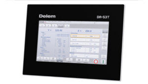
CNC – An acronym for Computer Numerical Control, a term applied to computer-controlled press brakes.
Crankshaft – The component of a mechanical press brake that transfers the energy of the flywheel to the ram.
Daylight Through – The term used to describe the maximum open position given a specific die set that a break can open.
Down Acting Brake – A press brake where the upper beam drives the punch downward.
Mechanical Stop – A physical stop that stops the old mechanical brake from tripping and improves repeatability.
Pinch Point – The moment the punch touches and starts applying tonnage to the workpiece. At this point, the back gauge can retract to allow the workpiece to form upwards freely.
Pit/No Pit Machine – Whether or not the machine requires holes in the floor and rafter base to stabilize and secure the lower beam. Pit machines are going to be much bigger than no pit machines.
Ram – Both the upper and lower rams are the driving or resistive components of the press brake. Typically machined from larger, stronger steel plates, they can be supplemented by internal hydraulic cylinders to resist the crown.
Repeatability – The accuracy with which the press brake can return to a speed state.
Stroke Length – The Brake Press’s maximum open size, defined as the distance between the top of the lower beam and the bottom of the upper beam when the brake is fully open and no tooling is installed.
Swing Up Fingers – The workpiece can whip upwards without damaging the back gauge allows to a special adaptation to the back gauge. These fingers can move freely with the part and out of the way.
Tandem – Two or more press brakes controlled by the same controller used to turn extremely large parts.
Throat – The depth of the press brake before the vertical support limits the flange length. Most press brakes are only obstructed by the neck of the brake around the driving cylinder.
Top Dead Center – Complimentary to Bottom Dead Center, this is the position of the press brake when it is opened to its maximum height.
Tonnage Control – The ability of a machine to control its tonnage up to its maximum tonnage. This is more in line with modern hydraulic brakes which can control its tonnage very precisely.
Up Acting Brake – A press brake where the lower beam moves the die upwards into the punch.
Upper Beam – The upper part of the press brake containing the punch holder.
X-Axis – Front to back movement of the back gauge. The X-axis controls the flange length, positive motion moves the rear gauge toward the operator and results in a shorter flange.
- X1 Axis – The front-to-back motion of the left-back gauge is independent of the right-back gauge.
- X2 Axis – Front-to-back movement of the right-back gauge independent of the left-back gauge.
- X1-X2 – The inclination of the back gauge forming an angled bend line with respect to the back of the workpiece.
R-Axis- Vertical speed of back gauge.
- R1 Axis – Vertical motion of left-back gauge independent of right-back gauge.
- R2 Axis – Vertical movement of right-back gauge independent of left-back gauge.
- R1-R2 – Inclination of the back gauge forming the vertically shifting backstop used for awkwardly turned workpieces.
Z-axis – Left-to-right movement of the back gauge. It is used when bending with multiple setups under the press brake, allowing the gauge to move with the operator as it moves the workpiece from one setup to another.
- Z1 axis – left to right movement left-back gauge.
- Z2 axis – left-to-right movement of the right-back gauge.
- Y-axis – vertical motion of the moving beam. It does not mean the speed of the back gauge.
These 45 brake press terminology will help you learn professional expression.